TOWARD AN ACCURATE TECHNICAL HISTORY OF THE WTC2 COLLAPSE
WTC2 BUILDING MOVEMENT: INDEPENDENT MAPPING AND MEASUREMENTS OF THE EARLIEST DETECTABLE MOVEMENT THROUGH THE COLLAPSE INITIATION SEQUENCE
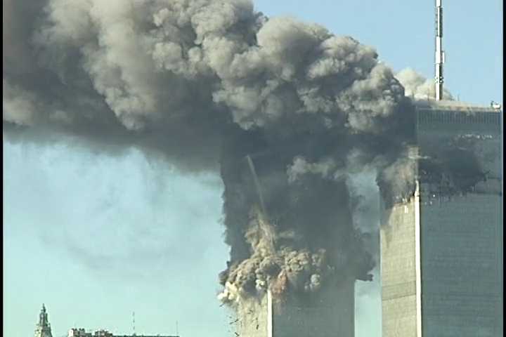
The collective visual record of the WTC2 collapse is examined directly and independently of all other sources, groups or individuals. The movement of the structure during the initial column failure sequence is mapped and traced back to the earliest point of detectable movement from multiple angles. Features of the initial failure sequence can be understood as a rapid succession of 8 identifiable events occurring in the following order:
Action above the 75th floor:
1) Deformations: Inward bowing of the east face
2) Earliest detectable movement: 81, 82nd fl spandrels pull in sharply (along east and north walls)......................
3) Earliest ejections, 78th fl ejections: .....................
4) East wall separates into upper and lower parts, East wall upper portion is pulled inward and behind the lower portion
5) Tilting begins
Flash and destruction of NE corner, floor 90
Failure sequence of the north and south perimeter walls over tilt of __ degrees
Action along the 75th floor:
6) 75th fl east face row of ejections
7) 75th fl west wall north and south quarter of MER panels ejected from building with flooring still attached. NW and SW MER corners are destroyed, west wall upper portion falls out and over lower portion.
8) Dropping of the upper portion.
All claims are verifiable and all methods reproducible.
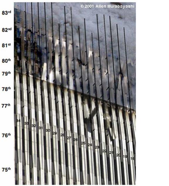
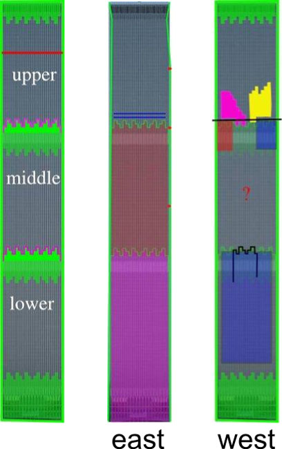
1) EARLIEST DEFORMATIONS: INWARD BOWING ON EAST FACE
Like WTC1, inward bowing was observed on the perimeter wall connected to long span floor trusses. In the case of WTC1, inward bowing on the south face led to collective core collapse at a tilt angle of less than 1 degree about 20 minutes after it was first observed. The actual tilt angle was grossly exaggerated within the NIST reports (shown in section 3.4), and upon this gross exaggeration the NIST concluded that south wall failure triggered collective core failure over a tilt of at least 8 degrees. If one uses correct observations and measurements as opposed to the grossly misrepresented ones offered by the NIST, it is natural to suspect that the south wall failure was a reaction to core failure rather than the other way around.
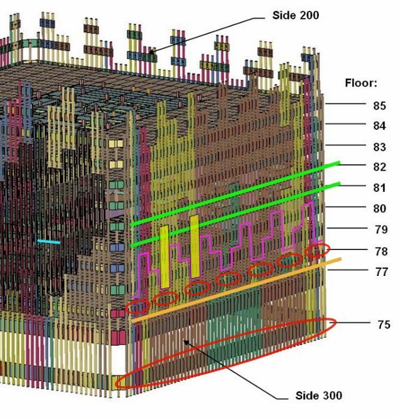
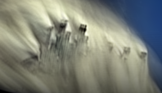
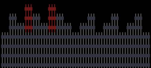
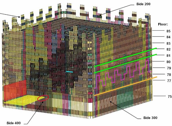
2) EARLIEST VISIBLE MOVEMENT: 81, 82nd fl spandrels pull in sharply (along green and blue lines)
The first visible movement leading into the collapse initiation sequence is that of the green and blue lines pulling inward and down sharply.
After that, 7 distinct ejections form along the 78th floor (marked by red ovals).
This is quickly followed by the east face breaking along the staggered purple line into upper and lower sections. The 2 yellow panels remain attached to the lower section (phenomenon #4).
All 3 actions are shown in the following video, occurring in rapid succession:
At the same time the green lines along the east wall are being pulled in sharply, a portion of the north wall is also being pulled inward as shown:
As will be shown in section 3.4, the NIST does not mention within their reports or seem to notice how the the north wall is pulled in along with the east wall. Just as in the case of WTC1 and WTC7, the motion indicates that the perimeter seems to be responding to failure within the core rather than the other way around.
In all 3 collapsed buildings, the NIST does not acknowledge that the perimeter deformation appears to be a response to partial or collective core action (shown in part 3).
This break pattern is the same as the purple staggered line shown in item #2 (earliest detectable motion), with the addition of 2 perimeter panels, shown as the off-colored panels in this illustration and shown as yellow panels in item #2.
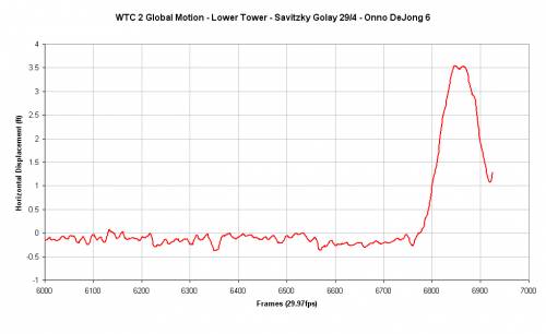
5) TILT BEGINS: DETERMINATION OF TILT OVER WHICH ALL COLUMNS INITIALLY FAIL:
The lateral displacement of the lower portion plotted:
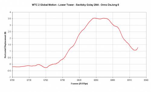
A stretched plot of the same motion:
Note that the displacement increases to a maximum, and then flattens out for a short time before returning. The end of the flat period occurs at frame 6873 on the graph. The building position at that moment is shown below:
The complete action through the portion of tilting in which the lower part of the building is being pushed outward to the west is shown:
This is the complete tilting motion which the building undergoes before the upper and lower portions become severed from one another.
4 distinct moments of building behaior are shown in the following gif:
Image 1 shows the moment the 78th fl row of ejections first become noticable.
Image 2 shows the moment just before the forceful 75th row ejections emerge. This is also the moment in which the upper and lower become completely severed from one another.
Image 3 shows the moment when the 75th fl ejection patterns become distinctly noticable
Image 4 shows the process of further downward movement.
Image 4 also marks the moment just before the west beam flooring from the mechanical equipment room (MER) levels will be propelled westward out of the building and the MER corner pieces will be ripped outward. The process is mapped in the next item.
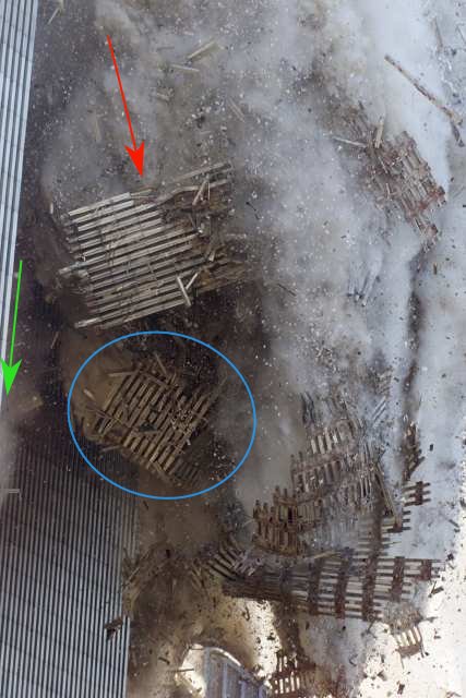
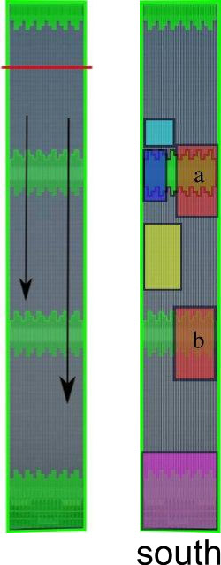
WEST WALL MER PANELS EJECTED WITH BEAM FLOORING ATTACHED
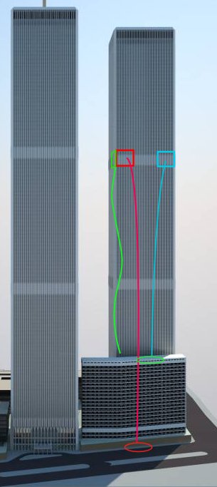
Just after the 75th floor east face row of ejections became visible in image 4 above, large sheets of flooring constructed of beams were ejected from the west side of the building with MER perimeter columns still attached. The location of one of the interconnected sections of MER perimeter columns with beam flooring is shown as a yellow and red plane in the graphic below:
The sheet of flooring was attached to core columns at the location marked by a red oval. The sections that were ejected with beam flooring still attached are shown as red and blue rectangles. They fell along the trajectories shown and landed in the positions indicated:
The green MER panel also fell according to the trajectory shown. The following video clips show the emergence of panel marked in red:
A slow motion version played forward and backward to show from where the panel emerges:
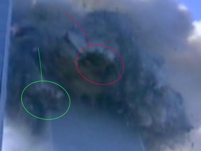
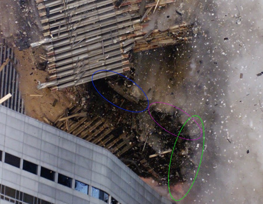
A still image extracted from the video shows the pieces marked in red and green falling:
A high resolution camera from another angle captures details of the MER perimeter pieces marked in red and blue leading other falling objects:
A bit later in the trajectory the same camera shows the falling MER perimeter sections in greater detail. Note the rectangular section of beam flooring still attached to the piece following the blue trajectory:
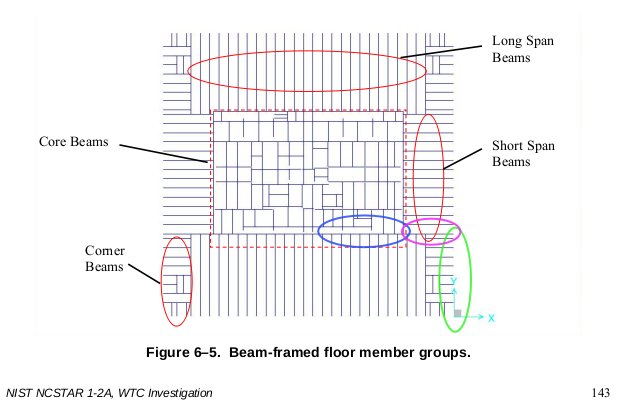
The edges of the flooring marked correspond to the sections of beam flooring marked in the following graphic. The graphic shows how beams are placed to support heavy equipment on the 75th floor (MER level):
The following link shows details of the upper and lower edges of each MER perimeter panel:
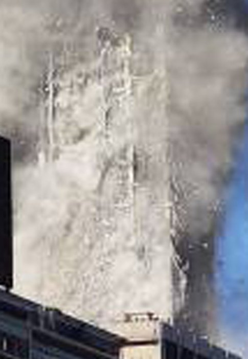
The upper portion falls completely behind the lower east perimeter wall and thrusts the lower wall outward:
The whole sequence described is visible. The ejection pattern along gthe east face is distinguishable as
Discontinuous and distinct row of 78th floor ejections
Discontinuous and distinct row of 75th floor ejections
Continuous flow of floor-by-floor ejection flow downward after the distinct and discontinuous row of 75th floor ejections.
The upper section breaks the final connections coupling it to the lower section just before the distinct row of 75th floor ejections emerges. It then falls downward behind the lower east wall, thrusting the intact lower wall out as a result as seen.
There is no need to speculate about these events since they are directly observable and captured in video and photographs, and therefore verifiable.
COLLAPSE PROGRESSION REVISITED: ORDERED DECONSTRUCTION (DECOMPOSITION) OF THE LOWER PORTION
WTC twin towers collapse progression was already described in section
Details of the core sections that temporarily survived the collapse viewed from the northeast.
The images available at this link allow the interconnected columns to be identified with certainty
RUBBLE DISTRIBUTION
RUBBLE LAYOUT
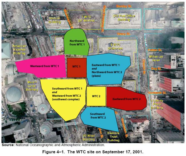
The debris for each building was found within and near the footprints and was pushed, or fanned outwards from the 4 exterior walls.
If WTC7 is ignored and only debris from WTC1 and 2 is considered, all debris exists in 8 natural regions as shown below.
Southward from WTC1 and westward from WTC2 share a region (called it "southwest complex") and eastward from WTC1 and northward from WTC2 share a region (the plaza area). Hence 8 natural regions total.
It is hoped that by rearranging all known useful debris photos by region, the reader can see for themselves how debris was distributed throughout the complex and in what condition without being overwhelmed with information.
All photographs of the debris are grouped according to location and type.
Just as with WTC1, WTC2 experienced inward bowing of the perimeter leading up to collapse. The reason given for this, according to the NIST, is that the perimeter was pulled inward due to sagging long span floor trusses. As with WTC1, vital clues are overlooked within the NIST reports that are extractable directly from the visual record.
Anyone can look at the splitting of the perimeter walls of each building to clearly see that WTC1 behaves quite differently than WTC2.
WTC 2: Observed Features of the Collapse Process (older links below may or may not work)