Twin Towers Perimeter Wall Collapse Model
 .........
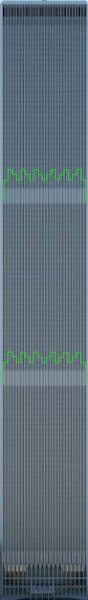
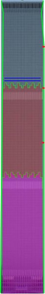
I can describe each of the 8 sides of the twin towers independently using this model. The green seams are important. They are the lowest bolted seam above the 2 central MER levels. They play an important roll in the overall perimeter motion.
Specific movement of each of the 8 sides show that key roles are played by 4 basic wall components:
1) The green bolt seams
2) MER perimeter panels
3) The 2 sides of each wall (corners of the building)
4) The large 30 floor sheets of standard perimeter panels between MER levels
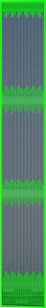
Stiff vs flexible
Each wall is stiffened by the corners and the MER panels. Even during and after collapse, MER panels and corners remained stiff while the large sheets of standard panels were flexible and bendable along spandrel plates.
Stiffeners
The green marks show the stiffest elements in the wall. MER panels are joined to ordinary panels through strong welds on upper and lower edges. The welds create a firm attachment extending the rigidity of the interconnected MER panels as shown.
The large areas of ordinary panels between the green stiffening plates are much more flexible when the green elements are removed.
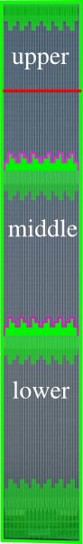
How can one determine where the lowest bolted connections just above the green stiffener plates are located? Shown here:
Determining Lowest Bolted Connections above MER Levels
General perimeter wall model
 ...........
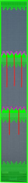
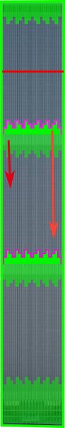
It is natural to divide the perimeter into 3 sections. The green MER bands play central roles in how the perimeter breaks up and falls.
Notice the WTC1 failure line is right in the middle of the upper section marked in red. The WTC2 failure line is along the upper edge of the 74-78 fl green belt marked in purple.
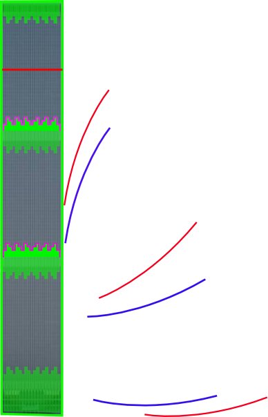
Dropping long and dropping short
The second drawing above shows the shedding of a large middle section perimeter sheet for WTC1 west wall (red) and WTC2 east wall (blue). Any individual wall will "drop short" or "drop long" depending how the middle section falls away from the building. In the cases of WTC1 west and WTC2 east, both "dropped long" as shown in the drawing. In both cases the green 74-78 fl MER belt plays an important role in keeping the sheets largely intact during the initial shedding.
Technique of dropping long: Example of WTC2 east wall.
 ......
Techniques of dropping short
 ...........
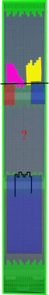
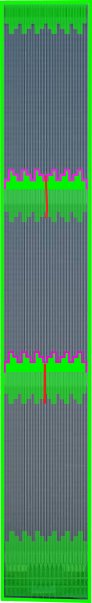
When dropping a whole sheet, it may be useful to make a single break through the middle of the green MER belt on either the 74-78 or 40-44 levels as shown in the first drawing. These breaks were witnessed on both upper and lower belts for WTC2 east and the wall dropped long in 2 sections.
In the second case the 74-78 MER belt is broken into 3 sections to cause fragmentation of the middle section. This would cause the wall to drop short.
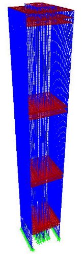
In the last case, this is the model for WTC2 west where the right and left quarters of the 74-78 MER belt shown in red and blue are forcefully ejected from the building with beam flooring still attached. This destroys the green MER belt, resulting in fragmentation of the wall down to the upper edge of the 40-44 fl MER belt. The lower wall survives the collapse of the building temporarily erect and then the lower blue section up to the 44th fl falls outward as a unit.
The pattern seems to be that by ejecting or fragmenting the 74-78th fl green MER belt, a wall can be dropped short by allowing the middle section to break into smaller pieces while being shed from the building. The survival of the 74-78th fl green MER band intact or broken down the middle allows the wall to be shed as a much larger piece causing the wall to drop long.
Uneven ROOSD progression allows large sheets to twist to the side rather than falling straight outward, shortening the distance of the drop.
Uneven ROOSD as reality
The simple truth is that we have witnessed 2 twin skyscrapers collapse and both did so through uneven ROOSD.
We have never seen a case of even ROOSD. As far as we know it can't happen.
The principle of uneven ROOSD is simplified below but there is no organized, stacked "pancaking". There is shattering and total disfiguration of OOS flooring, always unevenly according to the pattern shown:
It doesn't matter whether WTC1 or 2, the same uneven progression applies. OOS long span trusses are destroyed with a 10 to 20 story differential between leading region and lagging region.
The sides with short span trusses (WTC1 east and west faces, WTC2 north and south faces) are always stripped from the building unevenly creating a twisting motion in the sheets being shed.
The consequences of uneven ROOSD on wall shedding
We would expect perimeter walls to be shed differently depending on whether they are being stripped from the leading ROOSD front, the lagging ROOSD front or an uneven ROOSD front with a 10 to 20 story ROOSD differential.
3 natural types of perimeter wall behavior:
1) Wall with leading ROOSD front: WTC1 south and WTC2 east
2) Wall with lagging ROOSD front: WTC1 north and WTC2 west
3) Wall with uneven ROOSD (10 to 20 story differences at any moment): WTC1 east, west and WTC2 north, south.
Note the first 2 types experience even ROOSD stripping and can be expected to peel or break outward evenly.
The 3rd type of wall is subject to twisting forces as it is unevenly stripped from the building. It always twists toward the lagging side. These forces can be employed to drop a wall short, long or at an angle.
A sheet dropping at an angle using uneven ROOSD
 ..........
This actually happened to very large intact middle sections of WTC1 west and WTC2 east. The WTC2 east sheet was shown in the last post.
By disconnecting the right side of the sheet before the left side of the sheet at any elevation, it is easy to see how the whole sheet can be dropped at an angle as it twists early with one side still attached to the building a few moments longer than the other and continuing to twist in mid air while falling.
By using this technique along the south side of WTC2 as seen in the post before this one, a 110 story wall can be dropped very short before hitting the buildings just across the street.
Uneven ROOSD as a way to bias and steer the collapse
We all know that south side destruction led north side destruction for WTC1. This south bias changed the behavior of all 4 perimeter walls.
Likewise, WTC2 was biased toward the east. In both cases the bias happens toward a side with long span trusses and the sides with short span trusses have a tendency to twist away from the direction of bias.
In both cases, the lagging wall doesn't experience global "peeling" of the middle section. In both cases the base of the lagging wall survives erect, standing about 10 stories high. In both cases the leading wall was broken along the base under the tridents under street level.
There is very little doubt walls collapse in stages according to the 3 types ROOSD stripping I listed.
Attributes of a Rubble Driven Collapse
Models of Inelastic Accretion
If the towers were constructed 1000 stories tall and the same 12 story section as in the case of WTC1 starts to fall, it could destroy the whole building.
According to ROOSD, if the tower was 10,000 stories tall and of the same design, the top 12 stories could "crush" the 9,988 stories below.
Also, amazingly, bulky debris within the perimeter would stay confined to the tube while perimeter sheets opened outward and broke off at the base like petals of a tulip.
>>>>>>>>>>>>>>
The ROOSD paradox is that the height of the building does not matter. This is why 12 stories of WTC1 could "crush" the lower 98. The same 12 stories could have "crushed" 198 stories had the earth not stopped the process.
There is no paradox, obviously, but it is for those who see the buildings as "blocks" or a great buckling accordian. It also shows how easy it is for a demo team to use the ROOSD process.
They really do not care how high they are in the building, the higher the better.
Fundamental conditions for ROOSD
The most fundamental number relation for ROOSD is that...
Floor connection strength...... is much, much less than........ column buckling strength.
This is why ROOSD erosion can strip wall and core. They never compete because ROOSD stripping never threatens the column strength.
WTC 1: Recorded Motion of the Perimeter Walls
Images on right show identifiable and trackable large sections of the WTC1 south, north, and west perimeter walls marked by colored regions:
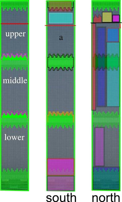
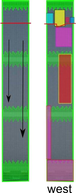
Fig 2.21 Each perimeter wall can be divided into 3 regions separated by reinforced MER spandrels. Collapse progression proceeds down different regions at different rates.
South Wall Collapsing
West Wall Collapsing
North Wall Collapsing
East Wall Collapsing
WTC 2: Recorded Motion of the Perimeter Walls
Images on right show identifiable and trackable large sections of the WTC2 east, west, and south perimeter walls marked by colored regions:
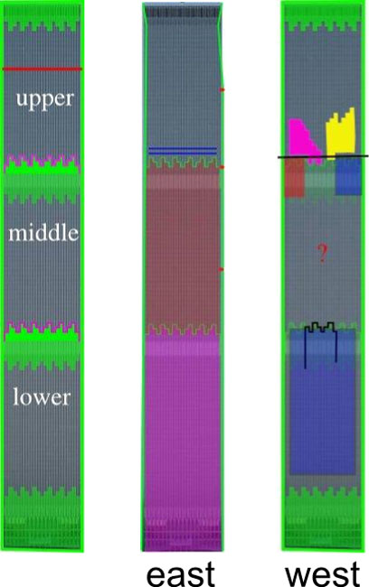
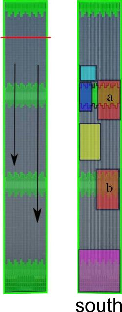
Fig 2.21 Each perimeter wall can be divided into 3 regions separated by reinforced MER spandrels. Collapse progression proceeds down different regions at different rates.
East Wall Motion
West Wall Motion
South Wall Motion
North Wall Motion
The case of the WTC2 east wall is a near perfect example of a perimeter wall breaking into large sections along the upper edge of the welded MER spandrel plates.
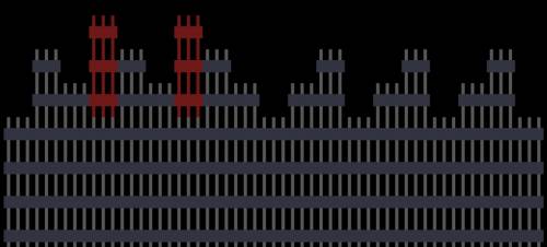
This is a diagram of the welded and reinforced MER perimeter sections and the layout of the lowest rows of bolted connections just above the MER panels.
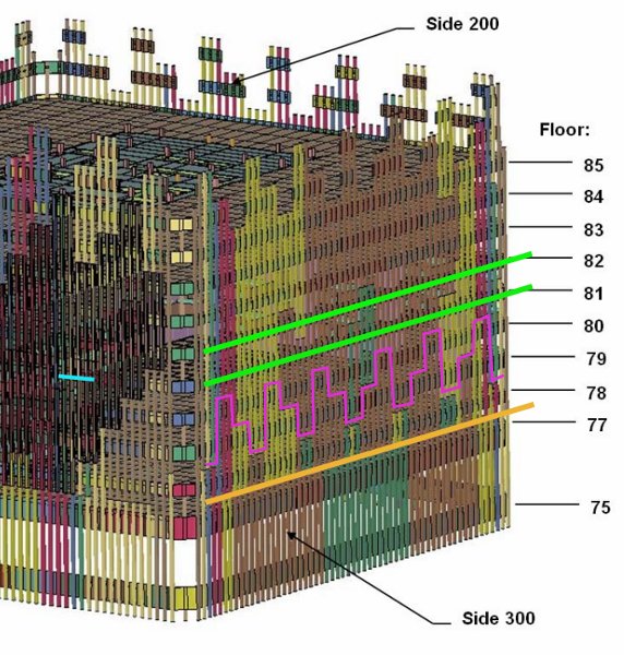
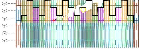
This is exactly where the actual perimeter broke into regions.
East Perimeter Snaps Cleanly Along Bolt Seams
The line of division between upper and lower wall is identifiable to individual bolted connections.
A still image from the animated gif reveals the break pattern:
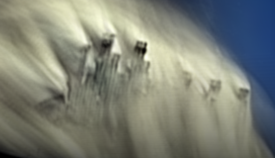
This is the exact outline of the upper edge of the east wall falling outward:
Larger version here
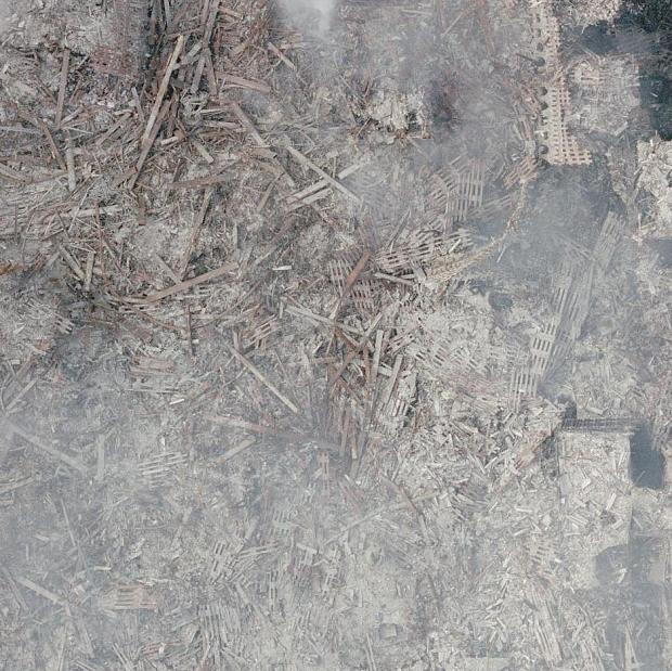
Observation of core and perimeter columns within the rubble
The overwhelming majority of core and perimeter columns within the rubble were were seen to be relatively straight, showing no evidence whatsoever of having been buckled. The almost complete absence of buckled columns is a vital clue to the true collapse progression mechanism, though the NIST seems oblivious to this fact, not having mentioned it once in in it's reports on the collapses. Dr Bazant, to whose expertise the NIST refers concerning WTC1 collapse propagation, seems equally oblivious to the actual condition of these columns since no mention of this fact appears of his papers on the subject of collapse propagation (Bazant and Verdure or Bazant and Le). Dr Bazant formulates equations to describe the rate of collapse propagation based on continuous column buckling and rebuckling in Bazant and Verdure, even though there is a clear absence of buckled columns within the rubble.
The true conditions of core and perimeter columns as they were positioned in the rubble can be seen by using the largest photo collection of the original layout of the rubble publicly available. Debris photos are grouped by region to allow the reader to get a sense of the rubble layout in each region without being overwhelmed or disorientated.
RUBBLE LAYOUT
As shown in Appendix B, the debris for each building was found within and near the footprints and was pushed, or fanned outwards from the 4 exterior walls.
If we ignore WTC7 and consider only debris from WTC1 and 2, all debris exists in 8 natural regions as shown below.
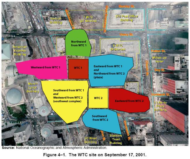
Southward from WTC1 and westward from WTC2 share a region (we'll call it "southwest complex") and eastward from WTC1 and northward from WTC2 share a region (the plaza area). Hence 8 natural regions total.
It is hoped that by rearranging all known useful debris photos by region, the reader can see for themselves how debris was distributed throughout the complex and in what condition without being overwhelmed with information.
The largest publicly available collection of debris photos are linked below:
Debris grouped by location:
Debris: WTC1 Around Footprint
Debris: WTC2 Around Footprint
Debris: From WTC1 Westward
Debris: From WTC1 Northward
Debris: From WTC2 Eastward
Debris: From WTC2 Southward
Debris: Plaza Area, Northeast Complex
Debris: Hilton Hotel, Southwest Complex
Debris: General, Unidentified Locations
Damage to Surrounding Buildings
Debris grouped by type:
Perimeter Column Photo Record
Perimeter Columns: Types of Damage
Core Box Columns: Types of Damage